When most people think of preventive maintenance and reliability procedures for a hydraulic system, regularly changing filters and checking the oil level are the only things considered. When the machine fails, there is often very little information about the system to refer to when troubleshooting. However, proper reliability checks should be done with the system running under normal operating conditions. These checks are vital for preventing equipment failures and downtime.
Check Hoses Regularly
Hose Condition
Leakage is one of the biggest problems in a hydraulic system. Proper hose assembly and replacement of defective hoses is one of the best ways to reduce leakage and prevent unnecessary downtime. Hoses should be inspected regularly for leakage and deterioration. Hoses that show wear on the outer jackets or leakage at the hose ends should be replaced as soon as possible. A hose that has “blisters” indicates a failure of the inner lining of the hose, allowing the oil to leak through the metal braid and collect under the outer jacket.
Hose Length
Whenever possible, hose length should not exceed 6 feet. Excessive hose length will increase the possibility of the hose rubbing against other hoses, a catwalk or a beam. This will lead to premature hose failure. In addition, when a pressure spike occurs in the system, a hose can absorb some of the shock. When this occurs, the hose length can change slightly. The hose should be made log enough so that it has a slight bend to absorb these shock spikes.
Hose Routing & Clamping
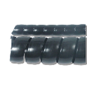
Where possible, hoses should be routed in a way that prevents them from rubbing against each other. This will prevent premature failure of the outer jacket of the hose. When it is not possible to route hoses to prevent rubbing, protective sleeves should be used. Several types of sleeves are commercially available for this purpose. Sleeves can also be made by cutting an old hose to length and slitting it lengthwise. The sleeve can be placed over the hose at the rub point. Plastic cable ties should also be used to fasten the hoses together. This prevents relative movement of the hoses at the rub points.
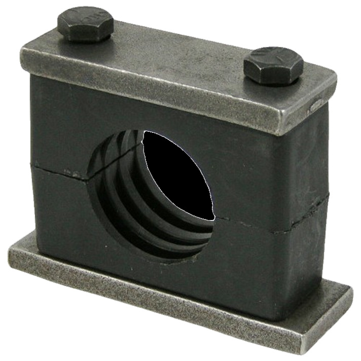
Proper hydraulic pipe clamps (like the one shown at right) should be used. Electrical conduit clamps are generally not acceptable for hydraulic lines due to the vibration and pressure spikes inherent in a hydraulic system. Clamps should be inspected regularly for loose mounting bolts. Broken clamps should be replaced. In addition, clamps should be properly spaced. A good rule of thumb is to space clamps approximately 5 – 8 feet apart and within 6 inches from where the pipe terminates.
Make Regular Drive Motor Current Draw Checks
The amount of power required to drive a hydraulic pump is dependent on the system pressure (PSI) and flow (GPM). As the pump wears, the internal bypassing increases due to increased internal clearances. This results in decreased pump output. With the pump delivering less flow to the system, the power required to drive the pump will decrease proportionally. Therefore, the drive motor current draw will decrease. Periodically making these current draw checks is an excellent way to track pump wear. A record should be made of the current draw when the system is operating normally to establish a baseline reference.
Make Regular Temperature Checks
All hydraulic system will generate a certain amount of heat during operation. This is because no machine is 100% efficient. As system components wear, the internal clearances increase. This leads to increased bypassing and whenever this bypassing occurs, excessive heat is generated. Heat does no useful work in the system. Therefore, energy is wasted. By using an infrared camera or some other type of heat detecting device, this excessive bypassing can be found. Bear in mind that heat is generated whenever a pressure drop occurs, so localized heat will always occur in any device that meters flow, such as a flow control or proportional valve.
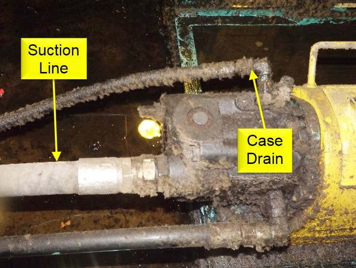
However, a hot relief valve or a severe temperature increase between a suction line and case drain line of an externally drained pump usually indicates a problem. Making regular inlet and outlet oil temperature checks on heat exchangers will give an indication of the heat exchanger’s overall efficiency.
In most cases, a hydraulic system’s reservoir oil temperature should be between 100°F and 120°F. High oil temperatures (above 140°F) can lead to chemical deterioration of the oil, as well as depletion of the additives. This will reduce the lubrication properties of the oil and lead to varnish buildup in the system. Furthermore, the seals in the cylinders and other components will suffer damage.
Listen for Abnormal Sounds
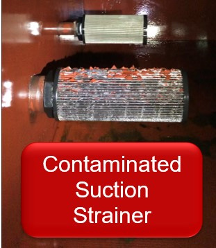
Regular sound checks should be made, especially with hydraulic pumps. Cavitation occurs whenever the pump cannot get the total amount of oil it is calling for at the suction port and will produce a steady high-pitched whining sound. If this is not corrected, the pump will deliver a reduced output until it is eventually destroyed. The most common cause of cavitation is a contaminated suction strainer. This is because many suction strainers are located in the reservoir and since they are “out of sight and out of mind” they are not typically serviced with the other system filters. Cavitation may also be caused by excessive oil viscosity (low temperature) or excessive drive motor RPM.
Aeration occurs whenever outside air enters the suction port of the pump. Aeration will produce an erratic sound, which can be described as “rocks going through the pump” or perhaps a “grinding” sound. Causes of aeration include and air leak in the suction line, low fluid level or a bad shaft seal on a fixed displacement pump.
Take Regular Oil Samples and Have Them Analyzed
From a medical perspective, it is important for each of us to have our blood drawn and analyzed, especially as we age. Doing so allows our doctor and other medical professionals to catch issues before they become more severe problems. Likewise, it is important to keep ourselves ahead of the game by analyzing our hydraulic system’s “lifeblood” (oil). A lab will analyze the sample for not only particulate contamination (as well as the types of particulate contamination present) but will also test the oil for water content, as well as oxidation and degradation among other things. It has been said that 95% of hydraulic component failures are caused by contamination. As someone who repaired hydraulic components for over 25 years, I can say this percentage is quite accurate. Therefore, taking regular oil samples and having them analyzed is a very effective tool for preventing component failure – and therefore downtime.