When servicing and troubleshooting hydraulic equipment, we all make mistakes. After all, we are human. These mistakes can cost us in many ways and almost always result from a lack of competent training. Working around hydraulic machines can be a complex exercise, as it involves a great deal of science. To avoid these common mistakes, a logical approach based on knowledge (including knowing the function of each hydraulic component) and sound troubleshooting principles is required.
Failure to Put Safety First!
Hydraulic systems operate at high pressures and flow rates. As a result, they have the inherent ability to burn, maim or kill. In addition, leakage of hydraulic oil can lead to slips and falls. However, knowing these facts as well as the function of each hydraulic component are only the “tip of the iceberg” when preventing accidents.
When working around hydraulic systems, the proper PPE (Personal Protection Equipment) must be worn. At a minimum, safety glasses or “full face” protection must be worn. Long sleeves and gloves should be worn to protect from burns and cuts. In addition, steel- or composite-toed safety shoes should be worn especially when replacing heavy components such as pumps and cylinders.
Since a great deal of energy is contained in a hydraulic system, most facilities will have LOTO (Lock Out / Tag Out) procedures to be followed prior to servicing the equipment. The goal of these LOTO procedures is to put the system in a “zero-energy state” to prevent the sudden release of energy. However, I know of many cases where these procedures were followed to the letter and personnel were still injured or killed while servicing a machine.
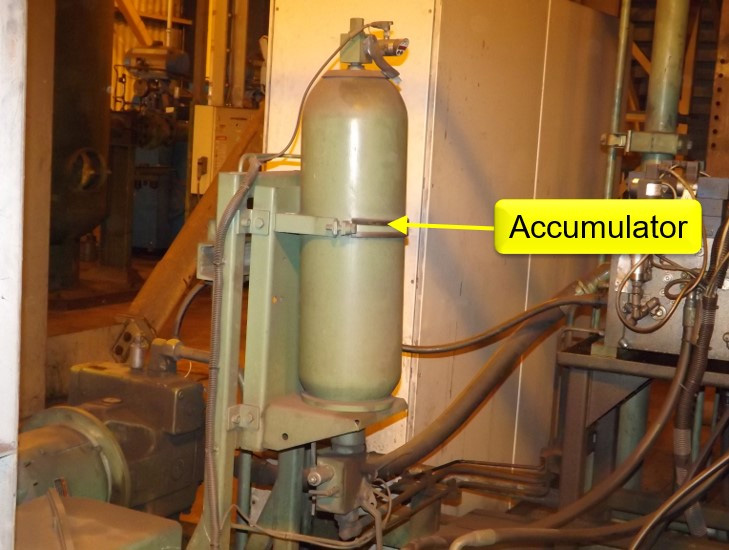
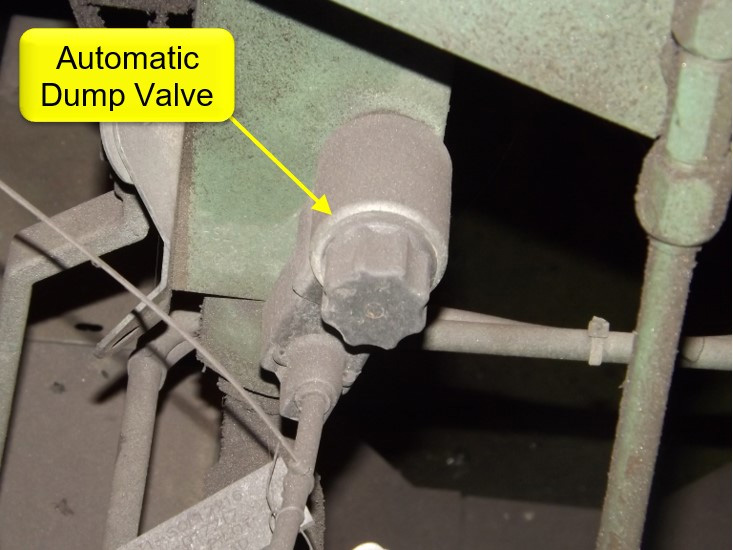
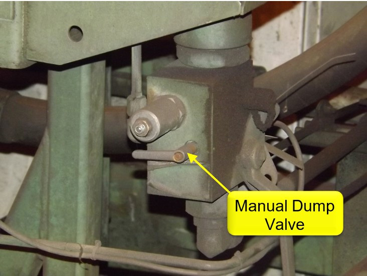
This is because of a lack of knowledge on the part of many people who write the LOTO procedures. They believe that their procedures are putting the machine in a zero-energy state, when there may in fact still be energy stored in the system. This is especially true wherever accumulators are used. Most systems will contain an automatic and/or manual dump valve (usually located in a block at the base of the accumulator) which will allow the pressurized oil in the accumulator to bleed to the reservoir when the system is turned off. If the automatic dump valve fails closed or the manual dump valve is not opened, pressurized oil will be maintained in the accumulator. If a line or component is removed, then someone may suffer an injection injury. Initially, an injection injury may seem minor. However, this is very serious as most hydraulic fluids are extremely toxic and any delay in proper medical treatment can lead to amputations or death.
One common mistake is to assume that if a pressure gauge reads zero pressure, then it is safe to remove lines and components. However, most systems will have a check valve for pump isolation, and the gauge is installed on the pump side of this check valve instead of the accumulator side. When the pump is turned off, the oil will bleed to the reservoir through the internal clearances in the pump. The technician will then think that the pressure is zero and will have no way of knowing if the pressurized oil in the accumulator has been released. On any system using this type of check valve, a gauge should be installed at or near the accumulator and a manual accumulator dump valve should be installed. Opening the dump valve should then become part of the LOTO procedures. This is the only way to be sure that all the energy has been released.
Misunderstanding of the Difference Between Pressure and Flow
Shell and Tube Heat Exchanger
As I spend time with plant personnel, I find that many people do not understand the difference between pressure and flow. Some even believe that pressure and flow are the same thing! This is why it is a common misconception that pressure must be increased to increase actuator speed. While it is true that pressure will increase actuator speed when standard (non-pressure compensating) flow controls are used, it is important to understand why this occurs.
One of the factors affecting the flow through a flow control is the difference between the inlet and outlet pressures. The pressure downstream of a flow control will be determined by the pressure required to move the load. This pressure will remain fairly constant, so long as the weight of the load does not change. The pressure at the flow control inlet will be at or near the pump compensator setting (when using a pressure compensating pump), so long as the pump can deliver sufficient volume. The difference between these two pressures is known as the pressure drop. Assuming the oil temperature and viscosity remain constant, an increase in pressure drop will result in increased flow through the flow control. This will in turn cause an increase in the actuator speed. The problem with this method is that the pressure has been increased well above the pressure required to do the work required. This only leads to shock and decreased component and hose life. It is also impossible to change the speed in one actuator without affecting the speed of the other actuators when using this method. When the speed of an actuator needs to be changed, it should only be done by adjusting the flow controls in the specific circuit. Just remember that the rate of oil flow controls speed, not pressure!
Another misconception pertains to the function of a hydraulic pump. I have found that about 60 to 70% of people believe that a pump makes pressure. This is understandable, as some so-called “hydraulic instructors” are teaching this to their students. In addition, a pressure compensated pump has an adjustment (compensator) that will change the pressure at the outlet of the pump, which adds to the confusion. However, this is simply NOT the case! The function of a hydraulic pump is to produce flow. As this flow produced by the pump encounters resistance, pressure will build. If you were to direct the pump volume directly to the reservoir, no appreciable pressure would be generated (as long as there is no resistance to the flow). It is important to remember that we must have two things to build pressure in a hydraulic system: flow (which the pump produces) and resistance (which is produced by the load). In the case of a pressure compensated pump, the pump will de-stroke to near zero volume when no flow is required.
Failure to Approach the Troubleshooting Process in a Logical Manner
When a machine failure occurs, many technicians will simply start changing parts until the machine starts working again. I discovered this in my 25+ years in repairing hydraulic components. I found that approximately 80% of the components I received for repair had absolutely nothing wrong with them! In our hydraulic troubleshooting workshops, we stress five elements necessary for troubleshooting and maintaining hydraulic systems:
1. Function
Knowing the function of each and every component is important.
2. Schematic
This is the first tool that should be used when troubleshooting a hydraulic issue. It is nearly impossible to determine the cause of an issue if one does not fully understand how all the components are interconnected.
3. On-Machine Troubleshooting
With a few exceptions, a hydraulic component can be tested without removing it from the system. This is facilitated by an understanding of the function and internal operation of various components.
4. Adjustment
It is very important to understand how to properly adjust the various components on the system. Having an improperly adjusted component is equivalent to having the wrong component installed.
5. Reliability Checks
Knowing the proper reliability checks to make can significantly reduce machine failures. These include temperature, pressure and speed checks. Of course, these checks should be made when the machine is operating normally to establish a baseline reference for future troubleshooting.
Installation of the Wrong Component
When a machine is not operating properly, there is usually only one component that has failed. Once that component is isolated, a replacement is sometimes selected simply because it looks the same and fits on the machine. However, pumps and valves can have many internal differences which can affect their operational characteristics. The model codes should be carefully compared, as each number or letter indicates a particular feature of the component. If there are any differences, then the manufacturer’s documentation should be consulted to determine what that difference is. On several occasions, I have traveled several hours to troubleshoot an issue only to find that the maintenance personnel had installed the wrong component.
When replacing a hydraulically piloted directional valve, careful consideration should be made as to the piloting configuration. These valves will have two additional ports in addition to the familiar “P”, “T”, “A” and “B” ports. One port will be marked “X” (pilot pressure) and the other will be marked “Y” (pilot drain). In an externally piloted and drained valve, the oil to and from the pilot valve is directed through these ports. If the valve is configured in this way and there is no pilot pressure at port “X”, the main spool of the valve will not shift and the actuator will not move. Many valve manufacturers use plugs inside the main body to change the piloting configuration. The manufacturer’s documentation will usually provide instructions for changing the configuration to the specific machine requirements.
Failure to Maintain the Reservoir and Associated Components
Most maintenance personnel do an excellent job at changing pressure and return filters at specified intervals. However, the reservoir is usually not given any attention. Reservoirs are normally sized according to the total pump volume, but the reservoir size is also factored in to determine how much heat is removed from the system during operation. The outside of the reservoir should be cleaned regularly to ensure that a portion of the heat in the oil is transferred to the atmosphere through thermal transfer.
One filter that is often overlooked during maintenance is the breather filter. Many see the breather filter as no more than a “cap” that can be removed for adding oil to the system. However, it is a filter and should be serviced as such. As the system operates and cylinders extend and retract, the oil level in the reservoir will rise and drop. As the oil level rises, air is ported from the reservoir to the atmosphere through the breather filter. Likewise, atmospheric air is drawn into the reservoir as the oil level drops. The breather filter prevents airborne contaminants in the air from entering the reservoir when this occurs. I recently did a reliability assessment on a loading system at a paper mill. I noticed that the breather filter was severely deteriorated and looked as if it had not been changed in quite a while. None of the maintenance personnel could tell me if or when the breather filter had been changed. Considering its condition, it is likely that the breather filter had been in place since the system was installed 34 years prior!
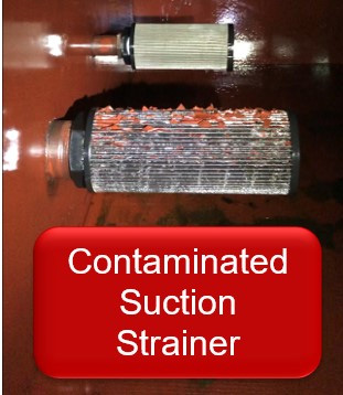
Many systems use suction strainers to prevent large particles from entering the pumps. These strainers are often located inside the reservoir, so they tend to go without service. However, if these strainers become contaminated, the vacuum at the pump suction will increase and cause cavitation of the pumps. This cavitation will lead to pump damage. Some time ago, I received a call from a customer in Ontario, Canada regarding a pump that had been replaced several times. Each pump was very noisy, and they were perplexed as to why the noise remained even after they changed the pump. Of course, I immediately suspected cavitation, so I asked them to drain the tank and inspect the suction strainer. They found the suction strainer (pictured at right) had become contaminated and was causing cavitation of the pump. The strainer was cleaned and their problem was solved. Of course, inspection and servicing of the suction strainers is now a part of their regular preventative maintenance procedures!
The Mistaken Belief That New Oil is Clean
Approximately 95% of hydraulic component failures are a result of contamination. One of the ways contamination can enter a hydraulic system is through adding unfiltered new oil. When hydraulic oil is first refined, it is relatively clean. However, once the oil is transferred to containers and transported, it can and will become contaminated. Several years ago, I received a call from a customer concerning a servo valve which I had repaired 8 years prior. He informed me that the valve had been in service all this time but had recently become very “sluggish” and eventually stopped working altogether. He advised that he was sending the valve in for repair, but that it was “no hurry” since he had a new valve that he had just installed and the system was again operational. Two days later, I received the failed valve for repair. I proceeded with an evaluation of the valve and found that the internal pilot filter was totally plugged with contaminants. I initially thought nothing of this since the valve had been in service for 8 years. However, I received yet another call from the customer advising that the new valve had failed after only three days! I asked if he had recently performed any maintenance on the system. He advised that they had recently serviced and cleaned the inside of the reservoir and had refilled the reservoir with new oil. When I asked him if the new oil had been filtered, he told me that it was new oil so it did not need to be filtered. This is a very common misconception and he was surprised to learn that he had inadvertently contaminated his system by refilling the reservoir with unfiltered new oil. In effect, he was effectively straining the contaminants in the oil through his servo valves.
Many systems incorporate a fill port for refilling the reservoir so that the new oil is ported through a filter. Standalone filter carts are also available for refilling the reservoir. Either way, any new oil added to the reservoir should be filtered. This is especially important on systems utilizing pressure compensated pumps and servo / proportional valves.
Although hydraulic machines have many advantages over other means of performing work, they are not immune to failures and downtime. The key to keeping them running is knowledge. In addition, most accidents can be prevented by a proper understanding of the fundamentals and science involved in hydraulic system operation.
