There is a common misconception that the maximum pressure in a hydraulic system using a pressure compensating pump is limited to the pump compensator setting. However, the compensator pressure setting merely determines the pressure at the outlet of the pump itself. Many people do not realize that the pressure at different points in a hydraulic system can be much higher than the pump compensator setting. This is due to several factors, one of which is pressure intensification in a hydraulic cylinder when using meter-out flow controls.
When a hydraulic system is supplied by a pressure compensating pump, flow controls may be connected in either a meter-in or meter-out configuration. When metering the flow going into a cylinder (meter-in), no pressure intensification will occur. However, this configuration provides less control over the cylinder speed due to overrunning loads. Therefore, metering the oil exhausting from the cylinder (meter-out) is more desirable in most cases. This is because the back pressure generated when metering the oil exhausting from the cylinder provides better control when an overrunning load is present. However, the back pressure is a cause of concern when pressure intensification is not taken into consideration. To understand how this can potentially be a problem, let us take a look at the sample system shown in Figure 1.
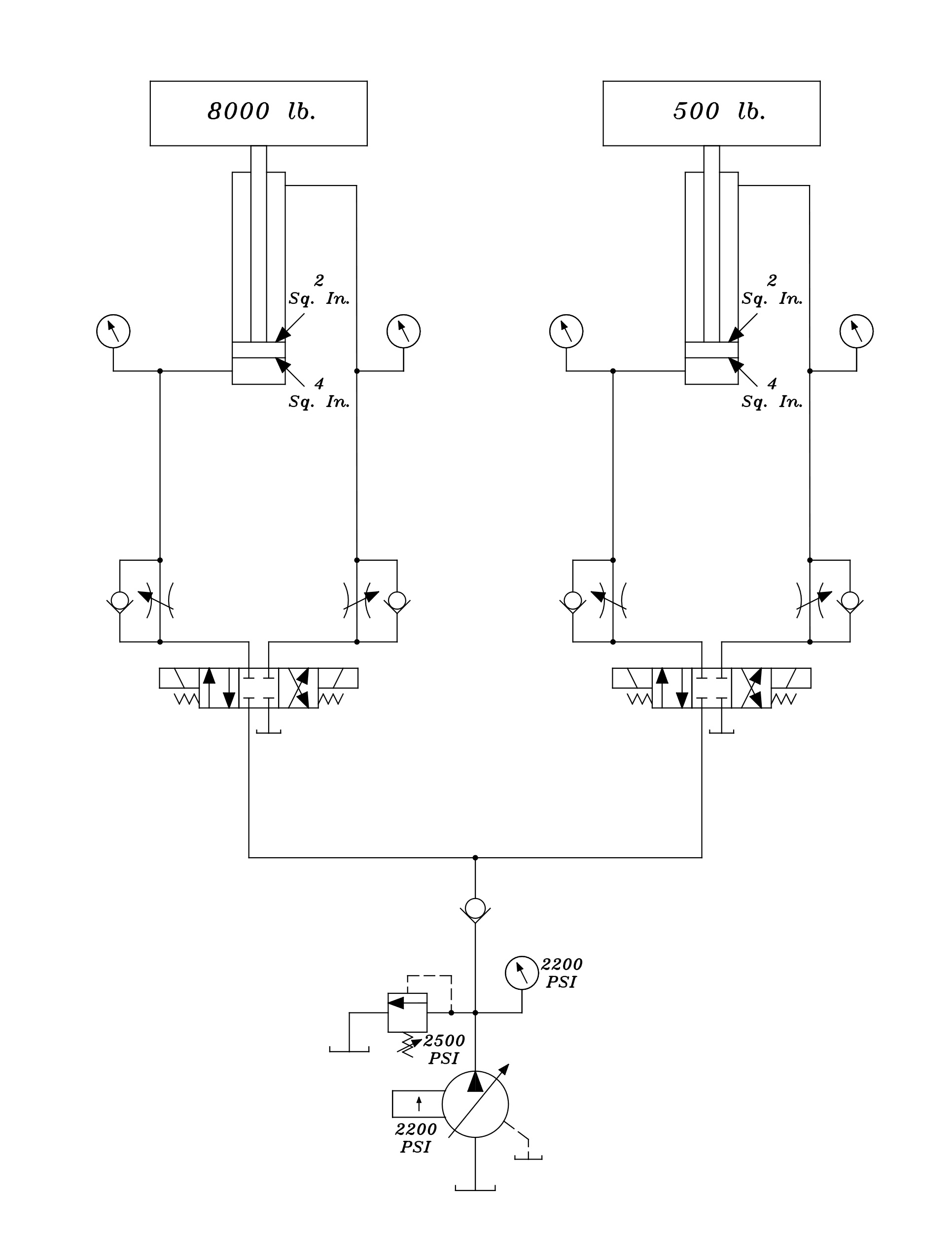
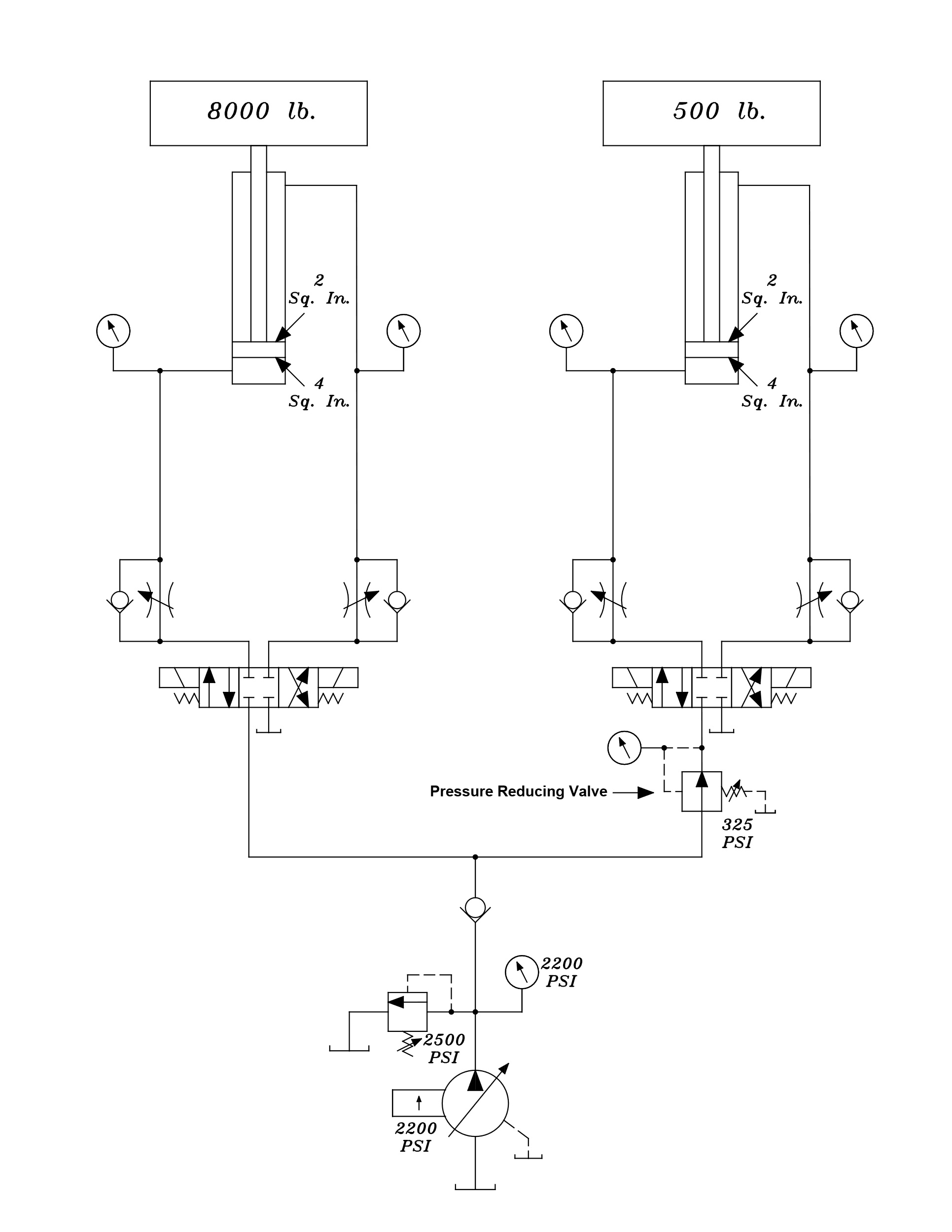
The two circuits in this system are identical except for the load on each cylinder. Each cylinder is identical, and the cylinder speeds are controlled using meter-out flow controls. The full piston surface area is 4 Sq. In. and the rod side surface area is 2 Sq. In. First, we need to take a look at the pressure settings of the pump compensator and the system relief valve and how we arrived at these settings. As mentioned previously, each cylinder has a different load; the cylinder on the left has a load of 8000 pounds and the cylinder on the right has a load of 500 pounds. We need to find how much pressure (Pounds per Square Inch) is required to move the heaviest load, which is 8000 pounds. To do this, we will use the following formula:
Force (Load) ÷ Area (Sq. In.) = PSI
or
8000 pounds ÷ 4 Sq. In. = 2000 PSI
Using this formula, we have determined that we will need 2000 PSI to move the heaviest load of 8000 pounds. Obviously, our pump compensator will need to be set above this “load” pressure in order for the cylinder to move the load. As a general rule of thumb, we will use a compensator setting 200 PSI higher than our load pressure. Therefore, in our example the compensator setting is 2200 PSI. The relief valve in this system is used as an extreme safety device and has been set 300 PSI above the compensator setting, or 2500 PSI. The relief valve should never open during normal operation, as it is set at a higher pressure than the pump compensator. It is only there to limit the pressure in the system in the event the compensator was to fail.
To understand the science behind pressure intensification, we will first take a look at what would happen if we extended the cylinder at no load with the aforementioned pressure settings. Please refer to Figure 2 below:
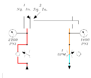
The pressure at the full piston side of the cylinder is at the pump compensator setting of 2200 PSI. This is because the meter-out flow control in the rod side of the cylinder has been set to 4 GPM, which is restricting the oil exhausting from the rod side of the cylinder. To determine the force generated by the pressure applied to the full piston side of the cylinder, we use the following formula:
2200 PSI (Pressure) x 4 Sq. In. (Area) = 8800 pounds (Force)
As mentioned above, the oil exhausting from the rod side of the cylinder is being metered by the meter-out flow control which generates a back pressure in the rod side of the cylinder. To find this pressure, we use the following formula:
8800 pounds (Force) ÷ 2 Sq. In. (Area) = 4400 PSI (Pressure)
With the cylinder doing no useful work (no load) we can see how the pressure is intensified due to the area difference between the full piston and rod sides of the cylinder. Of course, in practical application, the cylinder is doing useful work. In other words, it is moving a load. This illustration is given merely to demonstrate the concept of pressure intensification, which will also be affected by the actual load on the cylinder.
Next, let us take a look at what happens when we extend each cylinder with the loads applied. Please refer to Figure 3 on the next page. Once again, the cylinder on the left has a load of 8000 pounds. Using the previous formula, we find that the force on the full piston side of the cylinder is 8800 pounds. However, it only takes 8000 pounds of force to move the load. If we take the generated force and subtract the actual force required, we get a difference of 800 pounds. To determine the backpressure generated by the meter-out flow control (set at 4 GPM) we divide this difference of 800 pounds by the rod area of the cylinder (2 Sq. In.):
800 pounds (Force) ÷ 2 Sq. In. (Area) = 400 PSI
We can see that although a backpressure is generated by the flow control, it is relatively low due to the load moved by the cylinder. Now we will determine the back pressure generated in the rod side of the cylinder on the right, remembering that we must have a compensator setting somewhat above 2000 PSI in order to move the 8000-pound load on the left cylinder. Once again, the cylinder on the right has a load of 500 pounds. If we take the generated force and subtract the actual force required, we get a difference of 8300 pounds. To determine the backpressure generated by the meter-out flow control (set at 4 GPM) we divide this difference of 8300 pounds by the rod area of the cylinder (2 Sq. In.):
8300 pounds (Force) ÷ 2 Sq. In. (Area) = 4150 PSI
In this example, we can see that even though there is only 2200 PSI in the full piston side of the cylinder, the back pressure in the rod side of the cylinder has increased to 4150 PSI. This represents an increase of 1950 PSI!
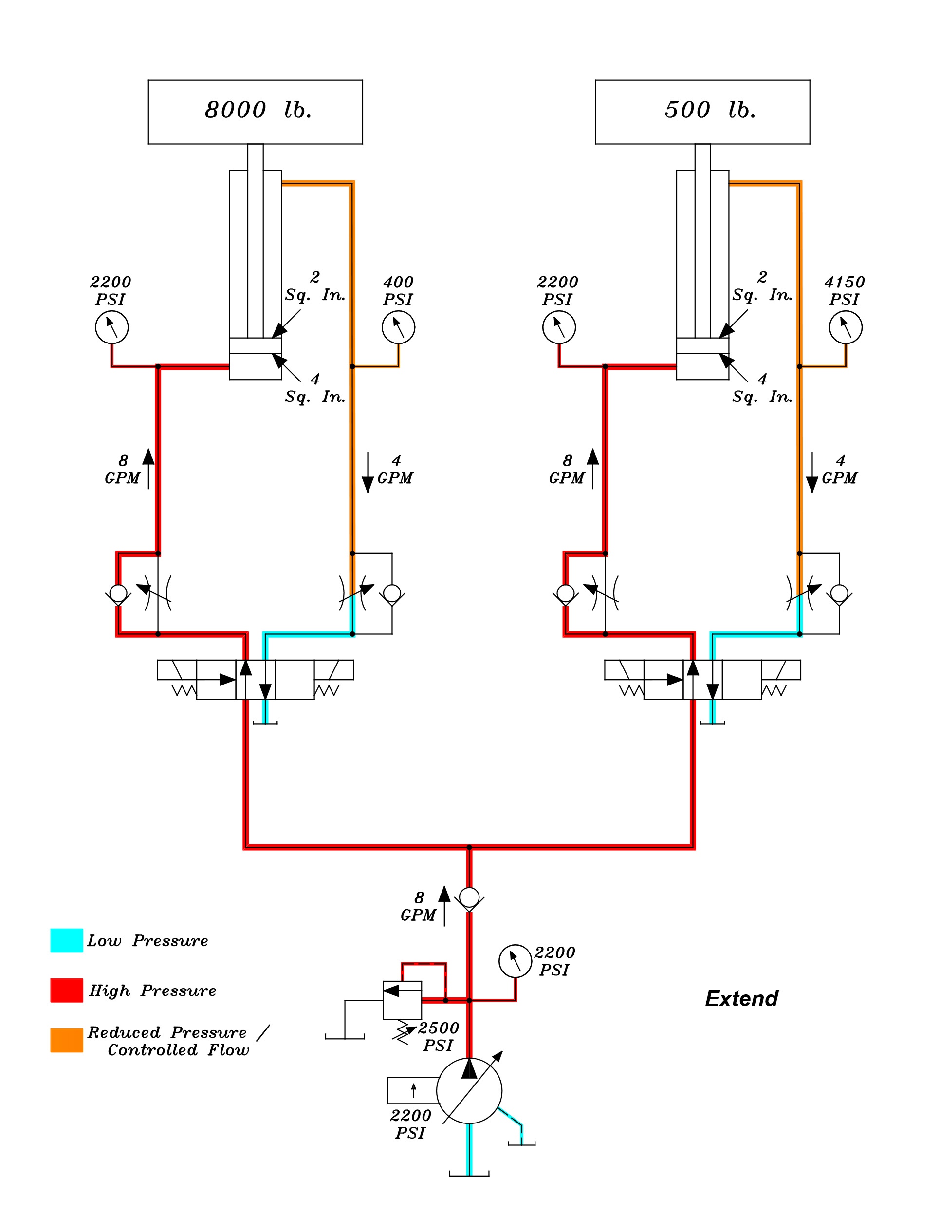
Assuming the cylinder on the right has a maximum pressure rating of 3000 PSI, one may initially think that this would be sufficient given the fact that the pump compensator is set at 2200 PSI. However, once we consider the pressure intensification caused by the meter-out flow control, we can see that the pressure in the rod side can go much higher than expected. This can cause premature failure of the cylinder, particularly in the rod seal and gland. Another factor to consider is that the tubing and hoses between the flow control and rod side of the cylinder may also see pressures in excess of their respective pressure ratings.
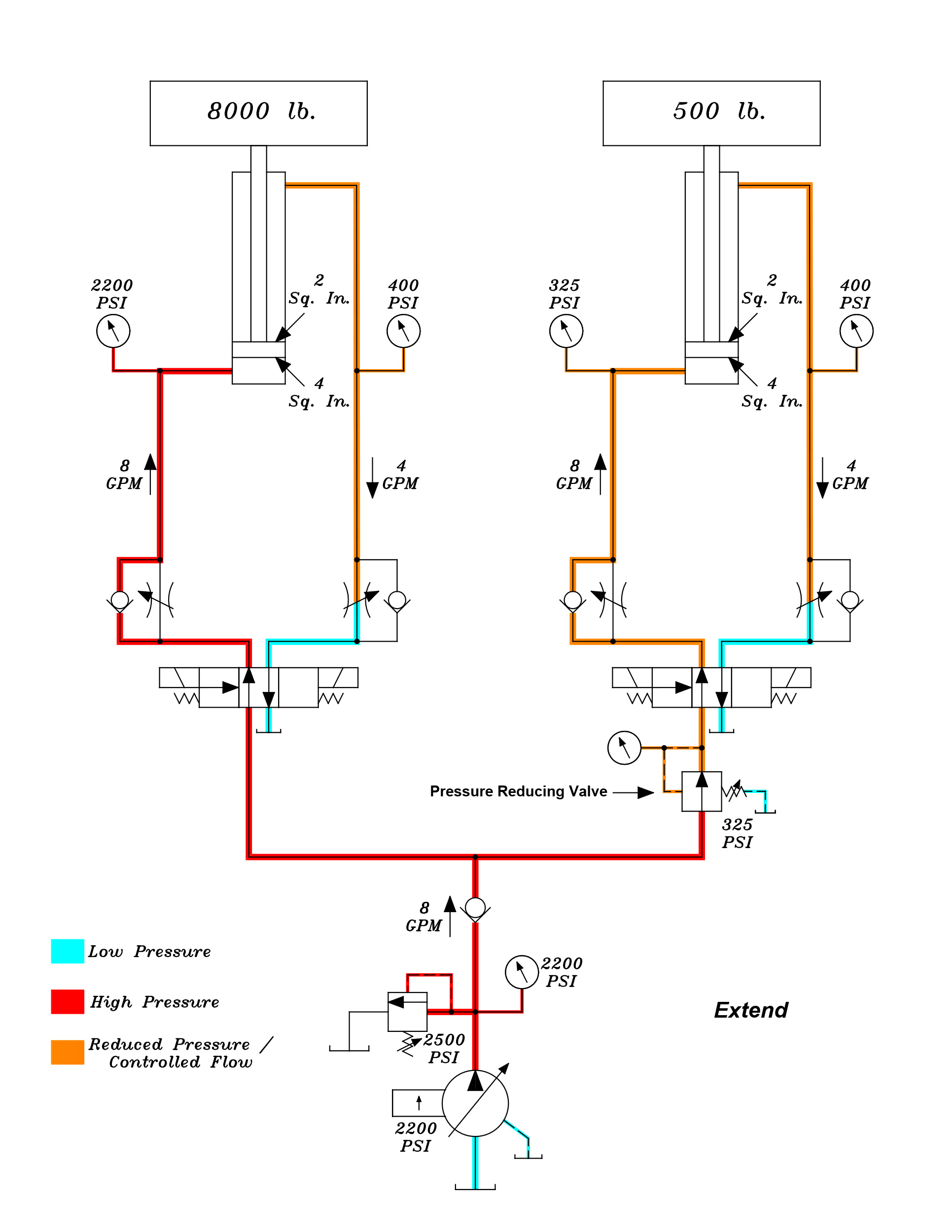
Now that we have seen how pressure intensification can occur in a hydraulic cylinder when using a meter-out flow control, how do we overcome the problem? First and foremost, pressures must be set accordingly. The pressure in a hydraulic system should be set according to the load being moved. Setting pressures too high will result in even more pressure intensification. In addition, shock in the system will be increased. In our example system, the pressure required to move the heaviest load (8000 pounds) is 2000 PSI, so the pump compensator has been set slightly above that pressure. In this case, the compensator has been set to 2200 PSI. This will give us sufficient pressure to move the 8000-pound load. However, only 125 PSI (500 pounds ÷ 4 Sq. In.) is required to move the load attached to the cylinder on the right. We need a way to prevent excessive intensification in this cylinder. Obviously, we cannot lower the pump compensator pressure as there would not be sufficient pressure to move the 8000-pound load. One viable solution would be to install meter-in flow controls. This option would also require installation of counterbalance valves to prevent uncontrolled cylinder speed due to the overrunning load. A more economical alternative would be to install a pressure reducing valve to lower the pressure in the cylinder on the right, as shown in Figure 4. Since it only takes 125 PSI to move the 500-pound load, we have set the pressure reducing valve to 325 PSI (125 + 200 PSI) to ensure that we have enough pressure to move the load. The pump compensator setting remains at 2200 PSI to ensure that enough pressure is available to move the 8000-pound load, but the pressure in the full piston side of the cylinder on the right is limited to 325 PSI by the pressure reducing valve. In Figure 5 on the next page, we will see the difference made by limiting the pressure in the cylinder with the lighter load.
Using the previous formula, we find that the force on the full piston side of the cylinder is now only 1300 pounds. However, it only takes 500 pounds of force to move the load. If we take the generated force and subtract the actual force required, we get a difference of 800 pounds. Once again, to determine the back pressure generated by the meter-out flow control (set at 4 GPM) we divide this difference of 800 pounds by the rod area of the cylinder (2 Sq. In.):
800 pounds (Force) ÷ 2 Sq. In. (Area) = 400 PSI
By installing the pressure reducing valve and limiting the pressure in the full piston side of the cylinder, we have greatly reduced the back pressure in the rod side of the cylinder while it is extending.
As we have seen, pressure intensification can cause damage to components. Another very important consideration is one of safety. In some cases, the pressure in the rod side of a cylinder may even increase above the 4:1 safety factor of a hydraulic hose as well as the hose ends and fittings, causing them to rupture. This could lead to personnel injury or death. When designing and maintaining hydraulic systems, pressure intensification must be taken into consideration and reduced where possible.